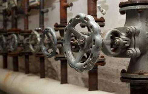
一、Precautionary measures for leakage and leakage of valves.
1. All valves must be subjected to different levels of hydraulic testing after entering the plant.
2. Valves that need to be dismantled for repair must be ground.
3. During the overhaul process, it is necessary to carefully check whether the packing is added and the packing cap is tightened.
4. The valve must be checked for dust, sand, iron oxide and other debris inside the valve before installation. If the above debris must be cleaned before installation.
5. All valves must be fitted with the appropriate level of gasket before installation.
6. The fasteners must be tightened when installing the flanged door. When tightening the flange bolts, the fasteners must be tightened in turn.
7. During the valve installation process, all valves must be installed correctly according to the system and pressure. It is strictly prohibited to install and mix. For this purpose, all valves must be numbered and recorded according to the system before installation.
二、Precautionary measures for coal powder leakage.
1. All flanges must be installed with sealing material.
2. The area where powder leakage is likely to occur is the coal inlet and outlet coal valve of the coal mill, the coal feeder, the manufacturer's flange, and all flanged parts. To this end, we will conduct a comprehensive inspection of all parts of the equipment that have the ability to leak powder. If there is no sealing material, we will install it twice and tighten the fasteners.
3. For the phenomenon that the pulverized coal pipe welding joint is willing to leak powder, we will take some measures.
3.1 Before the weld, the weld area must be carefully polished to a metallic luster and the groove required for welding must be ground.
3.2 The counterpart clearance must be reserved before the counterpart, and it is strictly forbidden to force the counterpart.
3.3 Welding consumables must be used correctly, and must be preheated as required in cold weather.
三、Precautionary measures for oil system leakage and oil running.
1. It is very important to do a good job of leaking oil and running oil.
2. The system with the oil storage tank must be carefully inspected and cleaned before installation.
3. Water pressure test must be carried out on equipment with oil cooler.
4. Hydraulic pressure test and pickling work are also required for the oil pipeline system.
5. During the installation of the oil pipeline, all flange joints or threaded joints must be fitted with oil-resistant rubber mats or oil-resistant asbestos mats.
6. Oil system leakage points are mainly concentrated on flanges and threaded unions, so the bolts must be tightened evenly when installing the flange. Prevent leaks or tightness.
7. In the process of oil filtration, construction workers must always stick to their jobs, and it is strictly forbidden to leave the post and to be separated.
8. It is necessary to stop the oil filter mechanism when replacing the oil filter paper.
9. When installing the temporary connection pipe of filter oil (high-strength plastic transparent hose), the joint must be tied tightly with the lead wire to prevent the oil from escaping after the oil filter machine runs for a long time.
10. Dispose of the highly responsible construction personnel to take care of the work of the oil filter.
11. Before the auxiliary oil system starts the oil circulation, the engineering department organizes a detailed technical briefing for the personnel responsible for the auxiliary oil circulation.
四、Eliminate the combination of equipment and fittings, such as foaming, dripping, and leaking. The following precautions are taken:
1. Flange gaskets above 2.5Mpa are all made of metal wound mats.
2, 1.0Mpa-2.5Mpa flange seal, using asbestos pad, and painted black lead powder.
3. The water pipe flange gasket below 1.0Mpa is made of rubber pad and painted with black lead powder.
4. The packing of the pump is made of PTFE composite packing.
5, the sealing part of the smoke and wind coal pipeline, the asbestos rope used is twisted once and flat, and the joint surface is added. It is strictly forbidden to tighten after tightening the screw.
五、The following measures are taken to eliminate the leakage of the valve:
(We should do the following for the leakage prevention of the valve)
1. Pipe installation and construction, must establish a good quality awareness, consciously clean the iron oxide skin and the inner wall of the pipe, leaving no debris, to ensure that the inner wall of the pipe is clean.
2. First ensure that the valve entering the site must be 100% hydraulic test.
3. Valve grinding should be carried out conscientiously. All valves (except imported valves) are required to be sent to the grinding class to dismantle the inspection and repair, and to implement the responsibility, consciously make records and marks for easy traceability. Important valves should be listed for detailed inspection and acceptance, so as to achieve the requirements of “printing, printing, and recording”.
4. The first water gate and discharge door of the boiler should be determined in advance. Only during the hydraulic pressure test, these valves should be opened. Other valves should not be opened at will, thus protecting the valve core.
5. When the pipeline is flushed, it should be opened and lightly closed to prevent damage to the spool.
If it is missing, why?
(1) the contact between the sealing surface of the opening and closing member and the valve seat;
(2) the combination of the packing and the valve stem and the stuffing box;
(3) The connection between the valve body and the bonnet
The leak in the former place is called endoleak, which is commonly referred to as the lack of tightness, which will affect the ability of the valve to cut off the medium. The latter two leaks are called external leaks, ie the medium leaks from the valve to the outside of the valve. External leakage can cause material loss, pollute the environment, and cause accidents in severe cases.
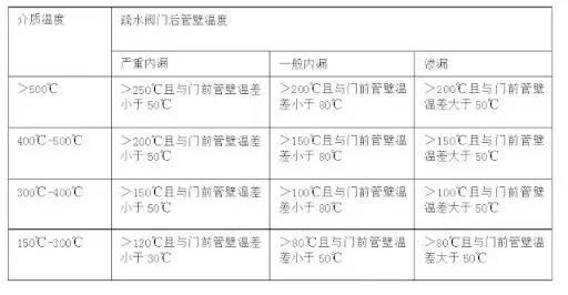
Fall in the real place, analyze the internal leakage, the internal leakage is generally:
Valves have different allowable internal leakage standards depending on their diameter, system pressure difference, and system media. In a strict sense, the valve of the true ‘0’ leak does not exist. In general, small-diameter shut-off valves are prone to invisible leaks (not zero leakage), while large-diameter gate valves are difficult to make invisible leaks. When encountering the internal leakage phenomenon of the valve, first of all, we should try to understand the specific internal leakage, check the allowable leakage standard of the valve, and comprehensively analyze the working environment of the system when the internal leakage occurs, in order to correctly judge the internal leakage of the valve. .
(1) Internal leakage of parallel gate valves.
The working principle of the parallel gate valve is to press the valve core and the valve seat sealing surface on the outlet side by the pressure difference of the system. When the system pressure is very low, there may be slight internal leakage after the valve. In the case of such an internal leakage phenomenon, it is recommended to continue to observe, check the sealing of the valve when the system inlet pressure reaches the design pressure or the normal working pressure. If there is still a leak exceeding the standard, it should be disassembled and the sealing surface of the valve should be ground.
(2)The inner leakage of the wedge gate valve.
Sometimes due to the different control methods of the valve, because the manufacturer selects the design, the corresponding valve stem and stem nut are the strength design without considering the torque control method, and the stroke control method is used, if forced, it will be closed. The position control mode of the position is changed to the torque control, which may cause damage to the valve stem nut, etc., and at the same time, the electric motor head may malfunction when it is opened, and an open torque failure alarm occurs. In the case of such an internal leakage problem of the valve, it can usually be turned off manually after the electric switch is closed, and it can be closed. If there is still an internal leakage phenomenon after the manual closing, it indicates that there is a problem with the sealing surface of the valve, and the disassembly grinding process is required at this time.
(3)The internal leakage of the check valve.
The sealing of the check valve also depends on the pressure difference of the system. When the inlet pressure of the check valve is very low, the outlet pressure will also rise slightly. At this time, various factors should be analyzed to determine the amount of leakage. The analysis structure determines whether the joint repair work is performed.
(4)The internal leakage of a large diameter disc valve.
The standard for internal leakage of large-diameter disc valves is generally large. When the inlet pressure is increased, the outlet pressure will also rise. For this problem, the amount of internal leakage should be judged first, and whether it should be repaired according to the amount of internal leakage. decision.
(5)Adjust the internal leakage of the valve.
Due to the different forms of the regulating valve, the standard for the internal leakage is also different. At the same time, the regulating valve generally uses the stroke control method (no torque control method), so there is generally an internal leakage phenomenon. The problem of internal leakage of the regulating valve should be treated differently. The regulating valve with special internal leakage requirements should be considered when designing and manufacturing. There are many such contradictions in the XX nuclear power plant. Many valves have to be changed to torque control, which is unfavorable for the operation of the regulating valve.
(1) The material selection and heat treatment of the valve trim are poor, the hardness is not enough, and it is easily damaged by high-speed fluid.
(2) Due to the limitation of the valve structure, the energy (speed) of the fluid is not effectively consumed when passing through the valve, and the impact wear force on the sealing surface is large; if the speed is too large, the pressure behind the valve is too small, lower than the saturation pressure, and cavitation occurs. During the cavitation process, all the energy is concentrated on the fracture point, and the impact force of several thousand Newtons is generated. The pressure of the shock wave is as high as 2×10³ MPa, which greatly exceeds the fatigue failure limit of the existing metal materials. Extremely hard discs and seats are also damaged and leaked in a short time.
(3) The valve works for a long time under a small opening state, the flow rate is too high, the impact force is large, and the valve inner part is easily damaged.

Reprinted from the Chamber of Commerce


